Wednesday, 6 April 2011

Evaluation and 'Moonraker' Animation

The opening scene of the animation is quite basic in terms of objects within the scene. However, the champagne bottle sliding across the table towards Bond visually indicates that this is Bonds assignment, reinforced by the narrative.
The second scene shows the shuttle travelling from the Earth towards the camera. The underside area of the shuttle model vertices became pulled during the modelling stage but without the time constraints and with the ability gained as the module progressed, a new shuttle model would have been created. An environment map background of a star scene was used in this scene and the remaining scenes.
The third scene introduced the space station which used the basic standard primitives to create the Spheres and arms for the model. The attach tool was used and a material was added.
The Moon and the Drax globe were also imported into the scene.
The fourth scene displays the Drax globe with Jaws and girlfriend inside travelling towards the camera to provide a close up view.
The fifth scene introduced the champagne bottle and the spray of bubbles. The animation of the bubbles is quite effective, however the motion of the champagne bottle is not smooth.
The sixth scene includes the same elements as the fifth scene but with the imported space shuttle and a smooth motion to the champagne bottle.
In the original film deadly nerve gas was sent towards the Earth in the Drax globe but in this animation its Jaws drinking Bonds favourite champagne inside the Drax globe on his way to the Earth.

Comment on colleagues work

Posted on Melissa Goddard's Blogsite.

I think you have made a fantastic job of using the reactor tool in such detail and applying this to the scene.


Posted on David Allison's Blogsite.

This is a stunning model, really impressive.

Saturday, 2 April 2011

Swot Analysis

Strengths

The opportunity to create physical mood boards enabled different film ideas to be considered. The chosen film idea was then translated into the modelling stage where the models that were created represented the mood board images reasonably accurately. Limiting the selection of models and condensing the story idea into six small scenes has made the animation manageable within the time available.
The tutorials, modelling and familiarisation with 3Dmax software has been a steep learning curve but I feel that I am gaining ability as time progresses.


Weaknesses

In order for the animation to be completed within the deadline the scenes have been condensed into manageable sections,where gaining familiarisation with 3D max has, in part, limited the creative process. However, each scene has contained the models and environment map required to portray the storyline. The scenes have also used cameras, path constraints, lighting, environment maps  diffuse bitmaps, raytrace refraction and particle generation.


Opportunities

The module has provided the opportunity to gain the foundations of a complex industry standard 3d modelling package. 


Threats

Threats to the animation involved problems with particular scenes. Examples include the image mapped onto the Drax globe would not render as an animation and the label on the bolinger bottle was blurred.

Biped and Physique Modifier

Skin and Bones
Cylinder created
System – Bones (inverse kinematics).
Click on mesh.
Skin modifier – add bones to skin.
Highlight bone four.
Move the nub.


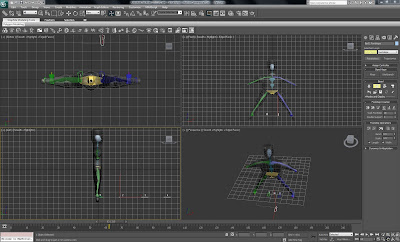
The biped and character studio is found under the systems rollout where the skeleton form may be modified under body type.
Physique
The model is placed in the Da-Vinci pose and see-through mode . 
(Object properties box).

 
Highlight mesh – modify panel – physique modifier.
The attach node button is clicked and the pelvis is selected. Orange lines should be displayed running through the biped.
Adjusting the envelopes
Selecting the mesh and changing to wire frame mode enabling the bones to be seen clearly.

Clicking on the yellow line running through the bones will activate the envelope.
Figure mode – enables scaling of the bones to fit the mesh.
Clavicle.
Highlight mesh.
Scale.
Physique  modifier.
Envelope – parameters – vertices turn red.


Envelopes affect mesh.

Biped walking
A bone is clicked on and the motion panel opens .
Under biped select   ‘Footstep mode’.
Under footstep creation select ‘Create multiple footsteps’.
A dialogue box is displayed that enables several parameters to be altered including the number of footsteps. Clicking ok and the footsteps will be automatically created.
Under footstep operations the ‘create keys for inactive footsteps icon must be clicked on.


Manual footsteps may be created by selecting a bone on the biped, clicking on footstep mode.
Then under  footstep creation, click on create footsteps (at current frame ) button.
Footsteps are then created by clicking in the top viewport.


Curve Editor


The function of the curve editor allows control of an objects trajectory by changing the tangency of the curve. To access the curve editor either click on the graph editors pulldown or click on the graph sign on the tool bar to display the function curve of the animation.

Drag a Sphere in the front viewport.

Turn on the Autokey.

Move Sphere to centre of bottom of viewport at keyframe 50.

Move Sphere to top right hand side of viewport at keyframe 100.

Right click on Sphere.

Object properties – click on trajectory.

( White boxes represent key frames for the animation ).

( White dots represent frames ).

The white dots are close together at the beginning of the trajectory and wider spaced in the middle at frame 50.

The animation is slow where the frames are close together.

The animation is fast where the frames are far apart.

The trajectory, presented so far in the animation requires correction.

The Sphere (bouncing ball) needs to start fast and accelerate when dropped from a height until frame 50 is reached.

At frame 50 the bouncing ball would bounce out fast loosing its acceleration by frame 100.

Using Key Tangencies the Tangency of the curve may be controlled by right clicking on the key at frame 50, Sphere 01 X position,  enables the Tangent to be changed to fast in and fast out.

To change the slope of the curve manually the use of the small handles will allow the curve to match the tangent chosen.

Clicking on the graph icon and the out of range Tangent Types dialogue box appears, which enables the animation to be stepped through or looping the animation.

Dope sheet

The Dope sheet may be accessed from the graph editors rollout and enables objects, animated tracks(transform track) and materials (material track) to be changed in a similar way to the curve editor. The keys in the animation are colour coded: Green – Rotation, Blue - Scale, Red – Move.
Selecting Filters on the left hand side of the dope sheet, the box is checked to 'show only selected objects and animated tracks'.
Clicking on edit ranges enables the black range bars to be viewed and subsequently moved.
Modify subtree enables the black range bars and the keys to be viewed together. The animation may be changed in the time line by moving the bars and keys.

Reactor


Introduction to Reactor.

Open the Reactor Toolbar (Left click blank area on right of top toolbar).

To access Reactor – Utilities panel – click on Reactor

Toolbar has six different fuctions: Reactor Collections, Reactor Modifiers, Reactor Objects, Reactor Constraints, the Property Editor and playback / animation tools.


Toolbar Buttons

Rigid body – Bricks tumble, skittles (rigid elements).

Cloth Collection.

Soft body collection.

Create rope.

Deforming mesh.

Helpers – Create plane etc.  Create water.

Constraints.

Modifiers – Cloth modifier.  Apply modifier first.

Open property editor – mass.

Analyse World.

Preview Animation.

Create Animation.


Using Reactor to create a snooker animation

A plane was used to create a snooker table surface. The snooker balls were created using spheres and the snooker cue was created from a cylinder.
The Spheres and cylinder were positioned and the Rigid body collection clicked on. The viewport was then clicked on and the Rigid body properties box is displayed. In the properties box click add and a selection box is then displayed. Highlight the Spheres and the cylinder from the list and press ok. The three objects are now in the properties box.
The properties editor is then used to alter properties such as mass and function. Unyielding should be checked to enable objects that are required to move to be free rather than fixed.
Keyframing was then used to animate the movement of the cylinder and Spheres. The final scene was then rendered as a avi file.