Lecture 3
Making your own materials
Downloaded 4 material images from the internet and saved as a 3cm*3cm bitmap.
Investigation into the various types of shaders.
Opened the material editor and clicked on one of the slots. Clicked on the small box next to the slot to reveal the material editor. At the top of the menu list is bitmap and when clicked on reveals a dialogue box. The dialogue box enables the bitmap images previously made in Photoshop to be found and when clicked on, subsequently appear in the material slot. Click and drag the slot image to the object in the perspective viewport.
Producing a Multi Sub-Object material
This section worked
Clicked and dragged the teapot into the perspective view.
Converted the teapot into an editable poly.
In the modify panel, check element.
Scroll down to polygon properties to material ID.
Click on the teapot spout and allocate ID 1.
Click on the lid and allocate ID 2.
Click on the belly of the teapot and allocate ID 3.
Click on the handle and allocate ID 4.
This is where it went wrong
Come out of editable poly.
Open the material editor.
Click on standard to pull up the procedural map menu> choose Multi/sub object> ok.
10 material slots appear. Select first four slots.
Click on material#standard – either add a map or make own material.
*** You then see these materials in the sample slot***!
Click and drag the sample slot to the teapot where the different materials are assigned to the different elements of the teapot.
Producing a High Shine metallic material
Need to try this
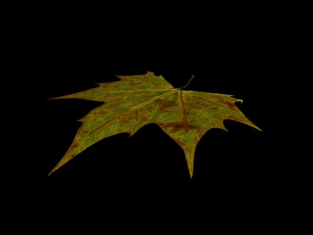
Making a leaf
Downloaded the tutorial and the map of the leaf.
Have yet to try this.
Response to the work on Richard Jones Blog ( Posted on his blogsite)
I think that Richard has organised the modelling of a complex structure,such as this aircraft, in a very clever way. He has broken the aircraft into component parts which has made the modelling process more manageable, rather than trying to model a complete aircraft structure. Modelling a structure in this way probably ultimately cuts down on the overall time required, as each component part is modelled on an individual basis and then brought together to realise the final 3d model.


 The material is then applied to the plane by clicking and dragging to the plane from the material preview slot. The map becomes visible in the viewport after clicking the show standard map in viewport chequered box.


 Create letter from shape text.


 The box shape was then converted to an editable poly and vertex tool selected. The vertices were then dragged, pushed and pulled to form the outline profile shape of the space shuttle.


